Samsung patents chip method using backside contacts for tighter circuits
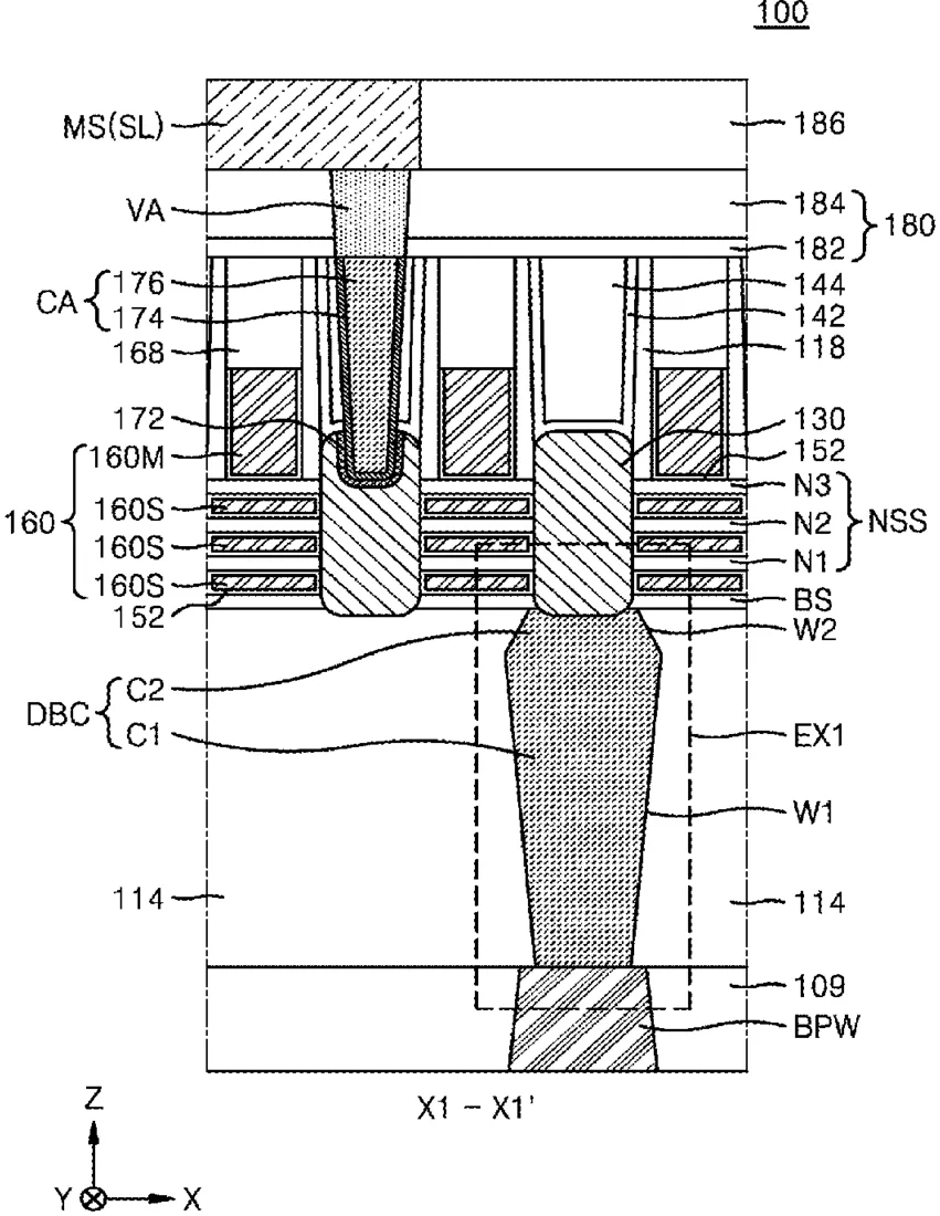
Samsung describes a way to build integrated circuits by creating narrow channels between raised sections of the chip material. The process uses temporary masks to carve out specific areas, allowing electrical connections to be made from the back of the chip rather than the front.
In the filing’s own words
A method of manufacturing an integrated circuit device includes forming an etch stop layer on a front-side surface of a substrate, forming a plurality of fin regions by etching each of the etch stop layer and the substrate, forming a first isolation insulating film covering sidewalls of each of the plurality of fin regions, forming a plurality of source/drain regions each on an etch stop layer, removing a portion of the substrate to expose a plurality of protruding portions, and to form a narrow space between two adjacent protruding portions, forming a blocking mask pattern in the narrow space, etching the plurality of fin regions, removing exposed portions of the etch stop layer to form an etch stop pattern, forming a plurality of second isolation insulating films, forming a contact space by removing the blocking mask pattern, and forming a backside contact structure in the contact space.
What exactly they claim (claim 1)
1. A method of manufacturing an integrated circuit device, the method comprising: forming an etch stop layer on a front-side surface of a substrate; forming a plurality of fin regions by etching each of the etch stop layer and the substrate, wherein the plurality of fin regions define a plurality of first trench regions and a plurality of second trench regions, a vertical level of a bottom surface of each of the plurality of second trench regions is closer to a backside surface of the substrate than a vertical level of a bottom surface of each of the plurality of first trench regions, and a portion of the etch stop layer remains on a top surface of each of the plurality of fin regions; forming a first isolation insulating film covering sidewalls of each of the plurality of fin regions, wherein the first isolation insulating film comprises a plurality of first portions filling the plurality of first trench regions and a plurality of second portions filling the plurality of second trench regions; forming a plurality of source/drain regions each disposed on the portion of the etch stop layer remaining on the top surface of each of the plurality of fin regions; removing a portion of the substrate from the backside surface of the substrate to expose a plurality of protruding portions of the plurality of second portions of the first isolation insulating film beyond the substrate, and to form a narrow space between two adjacent protruding portions among the plurality of protruding portions, the narrow space exposing a first fin region selected from the plurality of fin regions; forming a blocking mask pattern in the narrow space, the blocking mask pattern covering the first fin region; etching the plurality of fin regions around the blocking mask pattern by using the etch stop layer as an etch stop point to remain a partial portion of the first fin region covered by the blocking mask pattern between the etch stop layer and the blocking mask pattern; removing exposed portions of the etch stop layer to form an etch stop pattern and to expose a plurality of first source/drain regions among the plurality of source/drain regions while covering a second source/drain region among the plurality of source/drain regions with the etch stop pattern; forming a plurality of second isolation insulating films filling spaces defined by each of the first isolation insulating film, the etch stop pattern, the partial portion of the first fin region, and the blocking mask pattern; forming a contact space by removing the blocking mask pattern, the partial portion of the first fin region, and the etch stop pattern, the contact space exposing the second source/drain region; and forming a backside contact structure in the contact space.
Facts
- Company
- Samsung (Samsung Electronics Co., Ltd.)
- Official title
- INTEGRATED CIRCUIT DEVICE
- Publication number
- US20260313964A1
- Application number
- 19710969
- Filed
- Jun 17, 2026
- Published
- Oct 8, 2026
- Inventors
- 4
- Claims
- 20
Classified under
H10D 30/6729 Electricity & electronicsH10D 30/014 Electricity & electronicsH10D 30/43 Electricity & electronicsH10D 30/6735 Electricity & electronicsH10D 62/121 Electricity & electronicsH10D 64/01 Electricity & electronicsMore from Samsung in Chips & hardware
- Samsung patents chip that combines camera and screen Oct 13, 2026
- Samsung patents faster chip testing using machine learning Sep 1, 2026
- Samsung patents radar method to pinpoint target direction more accurately Sep 1, 2026
- Samsung patents memory chip that searches data by content, not address Sep 1, 2026
- Samsung patents chip design that skips empty data to speed up AI Sep 1, 2026
Summaries are simplified from the filing’s own abstract and first claim. A patent filing is not a product announcement.
Patent data and drawings: U.S. Patent and Trademark Office (USPTO). Nebula is not affiliated with or endorsed by the USPTO.