Samsung patents memory chip design with layered buffer structure
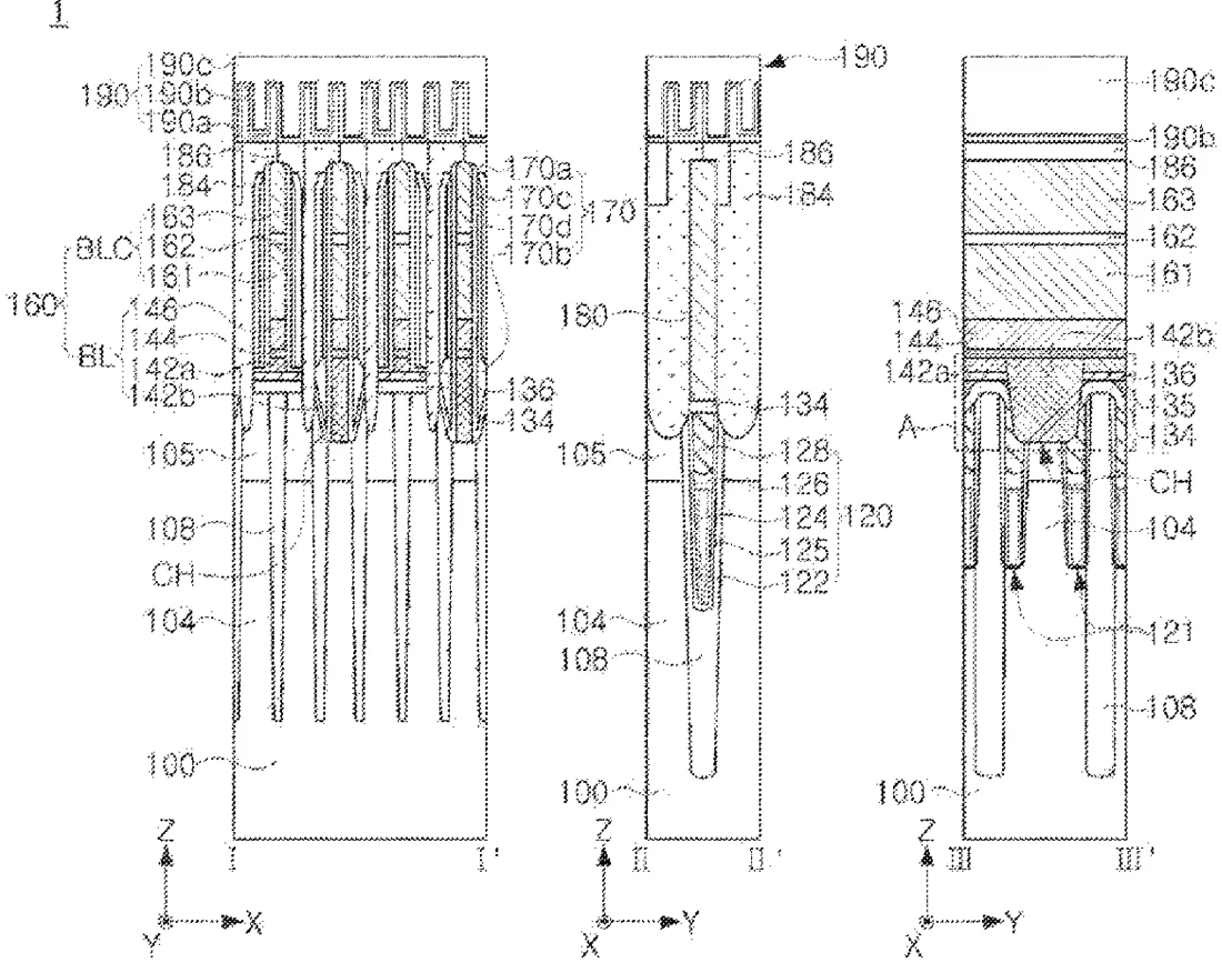
Samsung has been granted a patent for a semiconductor device that uses a specific arrangement of trenches and buried gates to create memory cells. The design features a multi-layered buffer structure that covers the active regions and gates, with specific patterns filling gaps to support the bit lines and storage nodes.
In the filing’s own words
A semiconductor device includes active regions defined by a device isolation region in a substrate; trenches extending in a first direction to intersect the active regions; buried gate structures buried in the trenches, respectively, and having upper surfaces located on a level lower than a level of upper surfaces of the active regions; a buffer structure covering the active regions, the isolation region, and the buried gate structures; bit line structures extending in a second direction intersecting the first direction on the active regions and connected to the active regions; storage node contacts between the bit line structures, penetrating through the buffer structure and in contact with the active regions; and capacitor structures in contact with an upper surface of the storage node contacts.
What exactly they claim (claim 1)
1. A semiconductor device, comprising: active regions defined by a device isolation region in a substrate; trenches extending lengthwise in a first direction to intersect the active regions; buried gate structures buried in the trenches, respectively, and having upper surfaces located on a level lower than a level of upper surfaces of the active regions; a buffer structure covering the active regions, the device isolation region, and the buried gate structures; bit line structures extending lengthwise in a second direction intersecting the first direction on the active regions and connected to the active regions; spacer structures that cover sidewalls of the bit line structures and are disposed on the buffer structure; storage node contacts between the bit line structures, penetrating through the buffer structure and in direct contact with the active regions; and capacitor structures in direct contact with an upper surface of the storage node contacts, wherein the buffer structure includes: a first buffer pattern extending along profiles of the upper surfaces of the active regions, the device isolation region, and the buried gate structures and having an upper surface including concave portions; a second buffer pattern including at least first portions filling the concave portions of the upper surface of the first buffer pattern, the second buffer pattern being in direct contact with the first pattern; and a third buffer pattern on the first buffer pattern and the second buffer pattern, the third buffer pattern being in direct contact with the second buffer pattern, wherein each of the bit line structures includes a first portion on an upper surface of the buffer structure and second portions penetrating through the buffer structure, wherein a lowermost portion of a lower surface of the second buffer pattern is at a vertical level farther away from a lower surface of the substrate in a third direction than a vertical level of a lowermost portion of a lower surface of the first buffer pattern, the third direction being perpendicular to the first and second directions, wherein an uppermost portion of an upper surface of the second buffer pattern is at a vertical level farther away from the lower surface of the substrate in the third direction than a vertical level of an uppermost portion of the upper surface of the first buffer pattern, wherein the lowermost portions of the lower surfaces of the first and second buffer patterns face the substrate, wherein the uppermost portions of the upper surfaces of the first and second buffer patterns face away from the substrate in the third direction, wherein the spacer structures are in contact with side surfaces of the first portion of the bit line structure, and wherein the third buffer pattern is in direct contact with a lower surface of the first portion of the bit line structure.
Facts
- Company
- Samsung (Samsung Electronics Co., Ltd.)
- Official title
- Semiconductor device having a buffer structure
- Patent number
- US12772437B2
- Application number
- 17880723
- Filed
- Aug 4, 2022
- Granted
- Oct 20, 2026
- Inventors
- 4
- Claims
- 20
Classified under
H10B 12/34 Electricity & electronicsH10B 12/053 Electricity & electronicsH10B 12/315 Electricity & electronicsH10B 12/48 Electricity & electronicsH10B 12/485 Electricity & electronicsH10W 20/092 Electricity & electronicsMore from Samsung in Chips & hardware
- Samsung patents chip that combines camera and screen Oct 13, 2026
- Samsung patents faster chip testing using machine learning Sep 1, 2026
- Samsung patents radar method to pinpoint target direction more accurately Sep 1, 2026
- Samsung patents memory chip that searches data by content, not address Sep 1, 2026
- Samsung patents chip design that skips empty data to speed up AI Sep 1, 2026
Summaries are simplified from the filing’s own abstract and first claim. A patent filing is not a product announcement.
Patent data and drawings: U.S. Patent and Trademark Office (USPTO). Nebula is not affiliated with or endorsed by the USPTO.