Samsung patents 3D memory design with tapered connections
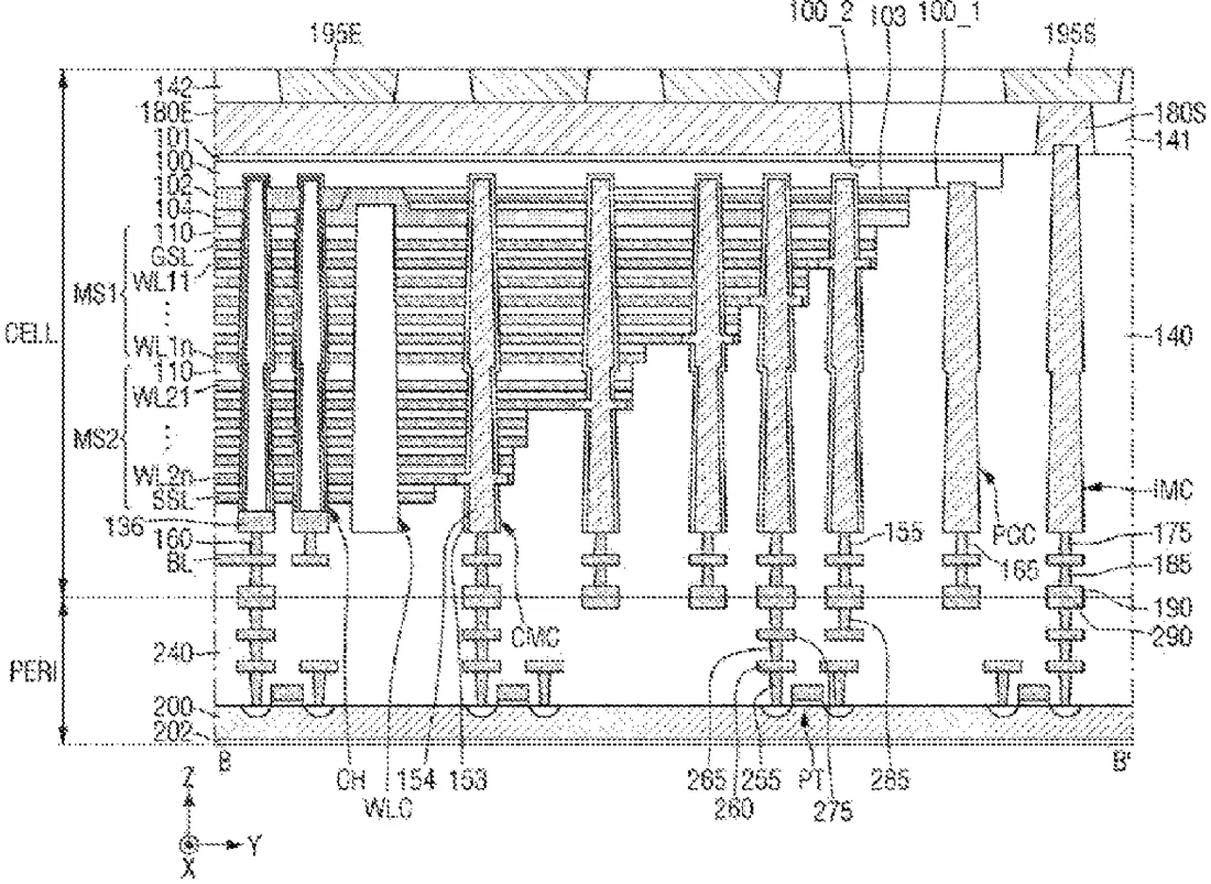
Samsung describes a semiconductor device where two substrates are stacked to create a 3D memory structure. The design features specific tapered shapes for the electrical connections between layers to improve stability and performance.
In the filing’s own words
A semiconductor device includes first and second substrates connected to each other. The second substrate includes a plate layer having first and second faces. Gate electrode layers are disposed on the first face of the plate layer. Channel structures extend through the gate electrode layers. Word-line cutting structures extend through the gate electrode layers and are spaced apart from each other. Via structures are disposed on the second face of the plate layer. Via connecting structures are disposed on the top face of the via structures. A width of the bottom face of each of the via structures is greater than a width of the top face of each of the via structures. A width of the bottom face of each of the via connecting structures is less than a width of the top face of each of the via connecting structures.
What exactly they claim (claim 1)
1. A semiconductor device comprising: a first substrate structure including a first substrate, circuit elements at least partially disposed on or in the first substrate, and first bonding metal layers disposed on the circuit elements; and a second substrate structure disposed on the first substrate structure, wherein the second substrate structure is connected to the first substrate structure, wherein the second substrate structure includes: a plate layer including a conductive material, the plate layer having first and second faces opposite to each other; gate electrode layers disposed on the first face of the plate layer, the gate electrode layers are stacked on top of each other in a first direction perpendicular to the first face of the plate layer and are spaced apart from each other in the first direction; channel structures extending through the gate electrode layers in the first direction; word-line cutting structures extending through the gate electrode layers, the word-line cutting structures extend in each of the first direction and a second direction intersecting the first direction wherein the word-line cutting structures are spaced apart from each other along a third direction intersecting each of the first and second directions and parallel to the first face of the plate layer, via structures disposed on the second face of the plate layer, the via structures extending in the third direction, wherein the via structures are spaced apart from each other along the second direction, each of the via structures includes a bottom face facing the second face of the plate layer and a top face opposite the bottom face; via connecting structures disposed on the top face of the via structures, the via connecting structures extending in the second direction, wherein the via connecting structures are spaced apart from each other along the third direction, each of the via connecting structures includes a bottom face facing the top face of the via structures and a top face opposite the bottom face; and second bonding metal layers disposed under the channel structures and the gate electrode layers and connected to the first bonding metal layers, wherein a width of the bottom face of each of the via structures is greater than a width of the top face of each of the via structures, wherein a width of the bottom face of each of the via connecting structures is less than a width of the top face of each of the via connecting structures, wherein in a plan view of the semiconductor device, the second substrate structure includes a first area including the channel structures, and second and third areas sequentially arranged outwardly from the first area, wherein the second substrate structure includes: cell contact structures disposed in the second area, each of the cell contact structures are electrically connected to one of the gate electrode layers; dummy channel structures disposed in the second area, the dummy channel structures are electrically isolated from the gate electrode layers; source contact structures disposed in the second area, the source contact structures do not extend through the gate electrode layers and extending through at least a portion of the plate layer; and through structures disposed in the third area, the through structures are not disposed on the plate layer, wherein the through structures are electrically connected to the circuit elements, wherein each of the via structures includes: a first extension disposed in the first and second areas and extending in the third direction; and a first spaced portion disposed in the third area and spaced apart from the first extension, wherein the first spaced portion is connected to one of the through structures.
Facts
- Company
- Samsung (SAMSUNG ELECTRONICS CO., LTD.)
- Official title
- Semiconductor device and electronic system including the same
- Patent number
- US12757711B2
- Application number
- 18197768
- Filed
- May 16, 2023
- Granted
- Oct 6, 2026
- Inventors
- 5
- Claims
- 16
Classified under
H10W 20/42 Electricity & electronicsH10B 43/27 Electricity & electronicsH10B 43/35 Electricity & electronicsH10W 20/20 Electricity & electronicsH10W 20/43 Electricity & electronicsMore from Samsung in Chips & hardware
- Samsung patents chip that combines camera and screen Oct 13, 2026
- Samsung patents faster chip testing using machine learning Sep 1, 2026
- Samsung patents radar method to pinpoint target direction more accurately Sep 1, 2026
- Samsung patents memory chip that searches data by content, not address Sep 1, 2026
- Samsung patents chip design that skips empty data to speed up AI Sep 1, 2026
Summaries are simplified from the filing’s own abstract and first claim. A patent filing is not a product announcement.
Patent data and drawings: U.S. Patent and Trademark Office (USPTO). Nebula is not affiliated with or endorsed by the USPTO.